Overview
Before going into the details of the configuration, let’s sum up what VSS is about.
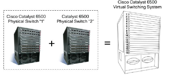
VSS stands for Virtual Switching System, it’s a virtualization technology that can be used on some platforms in order to merge the control plane of two equipment. This is very similar to a cluster except that the distance boundary is not set by the stack cable but by the maximum optical distance of the SFP.
VSS has some advantages above a “classic” dual system configuration.
- The configuration complexity is reduced as there is only one control plane to manage
- The system can trick other protocols to make the system appears as a single chassis (STP, LACP, FHRP…)
The system is more resilient as VSS relies on a 10G link, the distance between two equipment can be up to the distance of the optical link
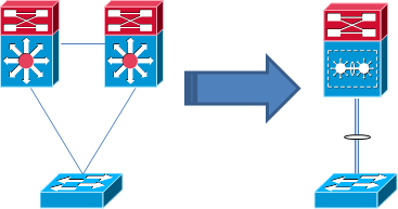
In a conventional distribution layer you would have two switches acting as L2/L3 boundary, from the access layer point of view one uplink will be blocked by STP for loop prevention and in case of failure you would rely on STP timers.
For gateway redundancy, FHRP needs to be implemented on the two switches and this can add latency in case of equipment failure. When you use a classic design, HSRP or VRRP only one gateway to be active. GLBP can give something that is more close to an active/active gateway behavior. In any case, this will add more traffic on the network.
With VSS, as the control plane is merged between the two devices, there is no loop, so STP is not actively needed (not actively here, HP tends to disable STP but not Cisco).
It still recommended to keep it activated though, just in case of a VSS failure. There is also no need for FHRP, the SVIs will be virtually present on both device. And last you can build an etherchannel that comes from the access layer and that ends on the two devices, LACP will not see anything, this is called MEC (Multi EtherChannel).
VSS is very useful at the distribution layer to go away from the traditional STP design.
VSS can also be used at the core layer, however this layer should already rely on layer 3 protocols and ECMP should already be performed there. VSS can still be convenient if the number of management point needs to be reduced.
The figure below shows the toplogy before VSS and after VSS.
At the time of this writing, VSS is available on Catalyst 6500 with SUP720-10G, Catalyst 6800, Catalyst 4500E with SUP7-E or 7-LE (or above) and Catalyst 4500-X.
VSL Link, a Very Special Link
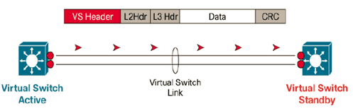
The VSL is the link that will be used to interconnect the two switches and merge the two control plane. VSL stands for Virtual Switching Link. Most platform will require at least 1*10G link to build it.
In any case it’s always desirable to have at least two interfaces to create the VSL. If possible this link should distributed among different line cards to avoid fate sharing if the line card that hosts the physical links goes down.
A new header is appended to every packet that need to go out the VSL link, this header is called the VS Header. This is a critical process as the data that will cross the VSL link will be considered as part a backplane extension. The introduction of this new header requires specific ASIC, so make sure that your line card are able to support it before trying to configure the VSL link on it.
VSS domain
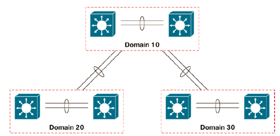
To form a VSS, two switches must be in the same VSS domain. The MAC address of the virtual system will be derived from the Domain ID.
The domain ID can be anything except when back to back connection of VSS system is required. In such case, the two pairs of Catalyst must have different domain IDs.
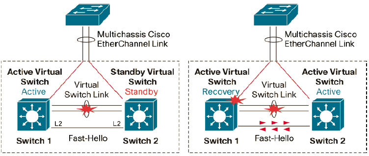
The Active/Active threat
If the VSL falls down, the two members of the VSS system will not be able to detect the status of their peer. They will consider the peer is down and they must act as the active supervisor of the VSS.
If the two members goes active, issues will arise. IP addresses which were configured on the SVIs will be duplicated, MAC address flapping will occurs, LACP bundles will be err-disabled… This is not a pretty scenario.
To prevent this, Cisco gives some tools that can be configured as a way to detect a dual active scenario in case the VSL goes completely down.
One method is called the Fast Hello. To configured this, you will need an additional port on each switch, this port can be 1G or 10G. Special packets will be exchanged through it to detect the loss of the VSL. If the VSL goes down, one switch will stay as the active supervisor while the other switch will go into recovery mode. This Fast Hello link must be a direct layer 2 connection between the two switches. Up to four Fast Hello links can be configured.
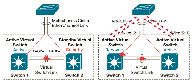
Another method is called Enhanced PAgP. This method will leverage the proprietary protocol that Cisco created in the past before LACP came. Special TLV will be carried through the MEC that is built with PAgP and each member will include in the TVL the Switch ID that it considers as the active one.
This advantage of this method is that it doesn’t require an additional interface but the switches that use PAgP must be Cisco Switches and they have to support PAgP.
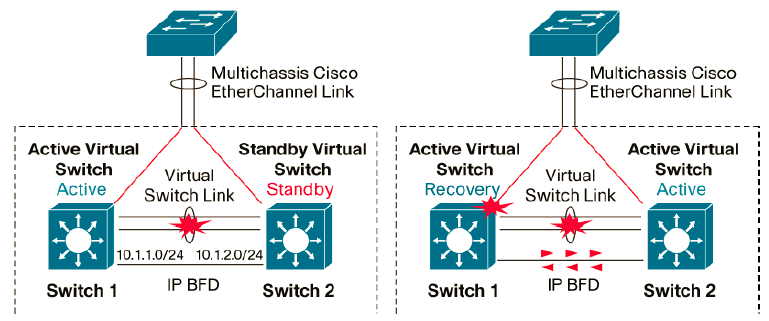
The last method available is IP BFD which is very similar to Fast Hello. If IP BFD is to be configured, a dedicated layer 3 link must be configured between the two switches. IP BFD allows for sub-second convergence.
Configuration of Cisco VSS
Configuration the domain ID
Switch(config)#switch virtual domain 10

Domain ID 10 config will take effect only after the exec command 'switch convert mode virtual' is issued

Switch(config-vs-domain)#switch 1 priority 255
Configuration of the VSL Link
In my test lab, there is only one 10G link between the two 4500-X. In production, you should always configure at least two interfaces for the VSL. Even if there is only one physical link here, I’m still required to build an port-channel.
Note that at this point the two control planes are not merged but they will be very soon. The port channel ID must NOT be the same or you will not be able to build the VSS. As a special control plane protocol will be used, the port channel must be configured in ON mode (static bundle).
The order of operation is important here:
- The Port Channel must be created first without any interfaces binded.
- The Port Channel must be configured as the VSL link
- Physical interface are bound to the Port Channel
4500-X1(config-if)#inter po1

4500-X1(config-if)#switchport

4500-X1(config-if)#switch virtual link 1

4500-X1(config-if)#inter TenGig2/1

4500-X1(config-if)#channel-group 1 mode on
The same operation needs to be done on the other switch
4500-X2(config)#inter po2

4500-X2(config-if)#switchport

4500-X2(config-if)#switch virtual link 2

4500-X2(config-if)#

4500-X2(config-if)#interface TenGig2/1

4500-X2(config-if)#channel-group 2 mode on
Note that the system will add a bunch of configuration both globally and on the interface:
interface TenGigabitEthernet2/1

switchport mode trunk

switchport nonegotiate

no lldp transmit

no lldp receive

no cdp enable

channel-group 1 mode on

service-policy output VSL-Queuing-Policy

end
There is also a series of class-maps and policy-maps that are added, you should not tamper with this configuration as this is related to the VSL link. Be careful on any changes you would like to make there.
Now the switches must be converted from standalone mode to VSS mode. This require a reboot to sync the configuration.
4500-X1#switch convert mode virtual

This command will convert all interface names

to naming convention "interface-type switch-number/slot/port",

save the running config to startup-config and

reload the switch.

Do you want to proceed? [yes/no]: yes

Converting interface names

Building configuration...

Compressed configuration from 5215 bytes to 2458 bytes[OK]

Saving converted configuration to bootflash: ...

Destination filename [startup-config.converted_vs-20140608-233732]?

Please stand by while rebooting the system...

Restarting system.
4500-X2#switch convert mode virtual

This command will convert all interface names

to naming convention "interface-type switch-number/slot/port",

save the running config to startup-config and

reload the switch.

Do you want to proceed? [yes/no]: yes

Converting interface names

Building configuration...

Compressed configuration from 5185 bytes to 2446 bytes[OK]

Saving converted configuration to bootflash: ...

Destination filename [startup-config.converted_vs-20140608-233741]?

Please stand by while rebooting the system...

Restarting system.
After the reboot, one switch should be active and the other should be standby. The status is pretty clear from the CLI:
4500-X1-standby>

Standby console disabled.

Valid commands are: exit, logout
Some manual verification can be made :
<4500-X1#sh switch virtual link
Executing the command on VSS member switch role = VSS Active, id = 1
VSL Status : UP
VSL Uptime : 6 minutes
VSL Control Link : Te1/2/1
Executing the command on VSS member switch role = VSS Standby, id = 2
VSL Status : UP
VSL Uptime : 6 minutes
VSL Control Link : Te2/2/1
4500-X1#sh switch virtual

Executing the command on VSS member switch role = VSS Active, id = 1

Switch mode : Virtual Switch

Virtual switch domain number : 10

Local switch number : 1

Local switch operational role: Virtual Switch Active

Peer switch number : 2

Peer switch operational role : Virtual Switch Standby

Executing the command on VSS member switch role = VSS Standby, id = 2

Switch mode : Virtual Switch

Virtual switch domain number : 10

Local switch number : 2

Local switch operational role: Virtual Switch Standby

Peer switch number : 1

Peer switch operational role : Virtual Switch Active
Also note that the interface denomination has changed and now includes the chassis number:
Te1/1/1 unassigned YES unset up up

Te1/1/2 unassigned YES unset up up
From there is you want to configure an bundle from a switch connected to the two VSS member, it needs to be configured as a regular port channel (using LACP, PAgP or static mode) as if it was a port-channel between two single switches.
For example I have a stack of 2960X connected to the two switches now in VSS. From the VSS control plane point of of view, the VSS switch is a regular switch:
4500-X1#sh cdp neigh

Capability Codes: R - Router, T - Trans Bridge, B - Source Route Bridge

S - Switch, H - Host, I - IGMP, r - Repeater, P - Phone,

D - Remote, C - CVTA, M - Two-port Mac Relay

Device ID Local Intrfce Holdtme Capability Platform Port ID

2960X Ten 2/1/2 131 S I WS-C2960X Gig 2/0/1

2960X Ten 1/1/2 174 S I WS-C2960X Gig 1/0/1

4500-X1#conf t

Enter configuration commands, one per line. End with CNTL/Z.

4500-X1(config)#int range t1/1/2 , t2/1/2

4500-X1(config-if-range)#channel-group 100 mode active

Creating a port-channel interface Port-channel 100
From the 2960X CLI, it is also a regular port channel:
2960X(config)#int range G1/0/1 , G2/0/1

2960X(config-if-range)#channel-group 10 mode active

Creating a port-channel interface Port-channel 10
Active / Active detection configuration
If you need to configure Active/Active detection configuration (you should do it), be sure to check first what can be done on you particular platform.
For example the 4500-X do not support IP BFD at the time of this wrinting. If you wan to use Enhanced PAgP, be sure that the remote switch is able to do it. It must be a Cisco Switch with the PAgP feature available .To be sure, check on the Cisco documentation and the Cisco Feature Navigator.
For example it's not possible to configure Enhanced PAgP when you have a stack of 2960X with uplinks going from different units to the VSS. This design is possible from 3650 and above though.
I will demonstrate here the Enhanced PAgP method by using a stack of 3850 connected to the VSS.
First you have to bring up a regular Port-Channel that use PAgP:
4500-X1(config)#inter range Te1/1/3 , Ten2/1/3

4500-X1(config-if-range)#channel-group 50 mode desirable

Creating a port-channel interface Port-channel 50

*Jun 9 00:12:13.789: %EC-5-BUNDLE: STANDBY:Interface TenGigabitEthernet1/1/3 joined port-channel Port-channel50

*Jun 9 00:12:14.584: %EC-5-BUNDLE: STANDBY:Interface TenGigabitEthernet2/1/3 joined port-channel Port-channel50
Once the PaGP interface is up you can configure the VSS to use it as the Active/Active link. You need to shutdown the port channel first and then configure it as the dual active mechanism
4500-X1(config-if)#inter po50

4500-X1(config-if)#shut

4500-X1(config-if)#switch virtual domain 10

4500-X1(config-vs-domain)#dual detection pagp trust channel 50
No action is required on the remote system. The following check can be made :
4500-X1#sh switch virtual dual-active summary

Executing the command on VSS member switch role = VSS Active, id = 1

Pagp dual-active detection enabled: Yes

In dual-active recovery mode: No

Executing the command on VSS member switch role = VSS Standby, id = 2

Pagp dual-active detection enabled: Yes

In dual-active recovery mode: No
As a test, you can shutdown the VSL link:
4500-X1(config-if)#shut

WARNING: You are shutting down one or more VSL interfaces.

If all VSL interfaces are down, connectivity between active

and standby switch (if present) will be lost and would also result

in two active switches. Traffic disruption will occur, and possible

configuration mismatch between the switches can happen.

Do you want to proceed? [yes/no]: yes

*Jun 9 00:17:37.343: %C4K_REDUNDANCY-3-SIMPLEX_MODE: The peer Supervisor has been lost

*Jun 9 00:17:37.379: %RF-5-RF_RELOAD: Peer reload. Reason: Active and Standby configuration out of sync

*Jun 9 00:17:37.379: %HA_CONFIG_SYNC-3-LBL_CFGSYNC: Unable to sync config-changed command(sh) to standby

*Jun 9 00:17:37.528: %PAGP_DUAL_ACTIVE-1-RECOVERY: PAgP running on Te1/1/3 triggered dual-active recovery: active id e02f.6d43.5520 received, expected e02f.6d43.5960

*Jun 9 00:17:37.549: %SW_DA-1-RECOVERY: Dual-active condition detected: Starting recovery-mode, all non-VSL interfaces have been shut down
4500-X1(recovery-mod(config-if)#
This switch is now in recovery mode while the other has taken the role of active supervisor. You have lost half the bandwidth but the nightmare scenario is avoided, there is no active/active condition.
Conclusion
VSS is a very useful trick for the aggregation layeras it allows us to move from the traditonnal STP design with its blocked ports and it helps reducing the number of management point
I cannot demonstrate everything about VSS here because the technology has been here for approx. a decade now and Cisco has improved it on the way. Some competitor do have the same kind of technology like HP with it's IRF or Huawei with it HVS but these technology are new compared to the Cisco VSS that is now a very mature technology.
The next post should be about a very nice technology which is called EVN !
Leave a Reply