Technology Overview
AToM stands for Any Transport Over MPLS. The goal behind this is to be able to transport any Layer 2 protocol over an MPLS Core. AToM is able to transport the following protocols over MPLS : Ethernet (EoMPLS), ATM, Frame Relay, HDLC and PPP. AToM is able to transport these protocols even if the terminating sides are not of the same type.
AToM will encapsulate the frame received on the ingress PE and sends it to the destination PE through a pseudowire. A pseudowire is a virtual connection between two PE devices. A pseudowire can only be a point to point connection. In the case of AToM the pseudowire is established by using targeted LDP session. When establishing a pseudowire, the following information must be specified :
- Type of Layer 2 that will be transported
- IP of the PE router which needs to be the MPLS ID of the remote PE
- A unique VC ID that identifies the pseudowire
MTU
As AToM encapsulates packet, MTU could become an issue at some point. The AToM header is 4 bytes and is called the control word. It is optional except for Frame Relay and ATM AAL5 where it is mandatory. The following table resumes the header size by transport protocol :

The MTU size that will need to be configured can be estimated by cumulating : The Edge MTU + The Transport Header + AToM Header + NbrOfMPLSLabel*4
Remember that the MPLS MTU must be less or equal than the interface MTU.
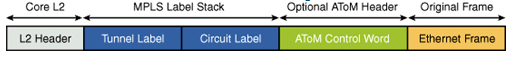
MPLS Stack
AToM will typically use two MPLS labels, the first one is the LDP label and the second one will be the VC label. More than two labels can be used it TE and LDP are used or if Fast Reroute is used.
AToM Modes
AToM can be deployed in two modes, Port Mode and VLAN Mode. This two mode are mutually exclusive on one interface. For example Port Mode cannot be configured on a sub-interface and VLAN Mode needs to be able to read 802.1Q label and uses sub-interfaces.
Port Mode
Configuring AToM in Port Mode effectively configure an EWS.
The customer will be able to forward its frame transparently from one CE to another, a trunk will be required between the PE and the CE.
VLAN Mode
Configuring AToM in VLAN Mode effectively configure an ERS.
The VLAN ID used by the service provider on the ingress interface on the PE determines the destination of the packet
Configuration Example
The following example shows AToM in VLAN Mode. Two customers are connecting two of their sites through the ISP, one of their requirement is to be able to mount an OSPF adjacency between their respective routers to manage the layer 3 routing.
The provider already has its MPLS core configured using OSPF, MP-BGP and LDP.

The configuration on the Customer router is very simple :
CustA1#sh run int f0/0
!
interface FastEthernet0/0
ip address 192.168.1.1 255.255.255.0
ip ospf 1 area 0
duplex auto
speed auto
end
CustA2#sh run int f0/0
!
interface FastEthernet0/0
ip address 192.168.1.2 255.255.255.0
ip ospf 1 area 0
duplex auto
speed auto
end
On the PE side, on sub-interface for each customer is configured with a different VLAN on each. The pseudowire is defined on the sub-interface through the xconnect command with the remote PE address and the VC ID :
PE1#sh run int F0/1.100
!
interface FastEthernet0/1.100
encapsulation dot1Q 100
xconnect 3.3.3.3 100 encapsulation mpls
end
PE2#sh run int f0/1.100
!
interface FastEthernet0/1.100
encapsulation dot1Q 100
xconnect 2.2.2.2 100 encapsulation mpls
end
On the example, the same VLAN is used on both endpoint so no VLAN rewriting is needed.
The pseudowire state can be checked :
PE1#sh mpls l2transport vc
Local intf Local circuit Dest address VC ID Status
————- ————————– ————— ———- ———-
Fa0/1.100 Eth VLAN 100 3.3.3.3 100 UP
Fa0/1.101 Eth VLAN 101 3.3.3.3 101 UP
Here he have two pseudowire, one for each customer established through LDP targeted sessions. More detailed information can be found on the pseudowire :
PE1#sh mpls l2transport vc detail
Local interface: Fa0/1.100 up, line protocol up, Eth VLAN 100 up
Destination address: 3.3.3.3, VC ID: 100, VC status: up
Next hop: 192.168.1.1
Output interface: Fa0/0, imposed label stack {16 16}
Create time: 01:14:36, last status change time: 01:14:10
Signaling protocol: LDP, peer 3.3.3.3:0 up
MPLS VC labels: local 16, remote 16
Group ID: local 0, remote 0
MTU: local 1500, remote 1500
Remote interface description:
Sequencing: receive disabled, send disabled
VC statistics:
packet totals: receive 206, send 212
byte totals: receive 55054, send 69876
packet drops: receive 0, seq error 0, send 5
The MPLS label stack can be seen on the information {16 16} and we can also find some of this information in the mpls forwarding table :
PE1#sh mpls forwarding-table
Local Outgoing Prefix Bytes tag Outgoing Next Hop
tag tag or VC or Tunnel Id switched interface
16 l2ckt(100) 62552 none point2point
17 16 3.3.3.3/32 0 Fa0/0 192.168.1.1
18 Pop tag 1.1.1.1/32 0 Fa0/0 192.168.1.1
19 Pop tag 192.168.2.0/24 0 Fa0/0 192.168.1.1
20 l2ckt(101) 21344 none point2point
So when the frame will be received on the interface for the customer connected through the VLAN 100, the remote PE will joined via the label 16 that will be used to form LSP. This will be the outside label.
To determine the interface where the frame needs to be switch on the other end of the pseudowire, the inner label will be used. Here 16 and 20 are defined for VLAN 100 and VLAN 101 respectively on PE1.
If we take a look at the communication on the ISP core, here is what we can find :

We can see the encapsulation done by AToM :
-
The two MPLS label are here, the outside label is used to determine the egress PE and the inside label is used to determine the VC ID
-
The PW Control Word is present and indicates 0
-
The original Ethernet Frame including the 802.1Q Tag and the OSPF MAC destination
Leave a Reply